Outline
- Impedance definition
- Analysis preparation
- Analysis configuration
- Anomaly detection
- Impedance analysis
- Result visualization
- Methodology and hypothesis
- Contribute to impedance analysis
Impedance definition
The impedance is the opposition to alternating current presented by the combined effect of resistance and reactance in a circuit. Commonly, in a battery it is defined by the voltage drop when a current is applied.
$$ Z= { \Delta U \over \Delta I }$$ with
- Z : the impedance (Ω)
- ΔU : the voltage variation (V)
- ΔI : the current variation (A)
In addition to resistance calculation, DATTES propose to model the impedance thanks to a constant phase element (CPE) or thanks the association of a resistance in parallel with a capacity (RC).
A CPE consists of non integer order impedance which is expressed in the frequency domain as:
$$ CPE(j\omega)={ 1 \over Q(j\omega)^\alpha}$$
with
- ω : the pulsation (rad.s-1)
- α : a real number comprised between 0 and 1 (-)
- Q : a constant (F.s^α–1)
A resistor–capacitor (RC) circuit is an electric circuit composed of a resistor and a capacitor.
Analysis preparation
DATTES is called as follows : [result]=dattes(XML_file,'action','configuration_file').
Before any analysis, it is then necessary to create the XML and configuration files.
The section Import cycler files explains how to create the XML file.
The section Create a configuration file explains how to create a configuration file.
Analysis configuration
DATTES enable users to define their preferences for analysis. For impedance analysis, the following fields from the configuration file should be defined :
| Configuration structure | Field | Array | Unit | Description |
|---|---|---|---|---|
| config | resistance | delta_time |
s | Instant at which resistance is determined |
| config | resistance | pulse_min_duration |
s | Minimal duration for the pulse considered by identification |
| config | resistance | pulse_max_duration |
s | Maximal duration for the pulse considered by identification |
| config | resistance | rest_min_duration |
s | Minimal duration for the rest before the pulse considered by identification |
| config | impedance | indent_fcn |
@ident_cpe or @ident_rrc |
|
| config | impedance | pulse_min_duration |
s | Minimal duration for the pulse considered by identification |
| config | impedance | pulse_max_duration |
s | Maximal duration for the pulse considered by identification |
| config | impedance | rest_min_duration |
s | Minimal duration for the rest before the pulse considered by identification |
| config | impedance | fixed_params |
True if you want to fix parameters for identification | |
| config | impedance | initial_params |
Initial value for model parameters | |
| config | impedance | min_params |
Minimal value for model parameters | |
| config | impedance | max_params |
Maximal value for model parameters |
Anomaly detection
Impedance tests may be affected by poor detection of a measurement as well as noisy current and voltage measurements.
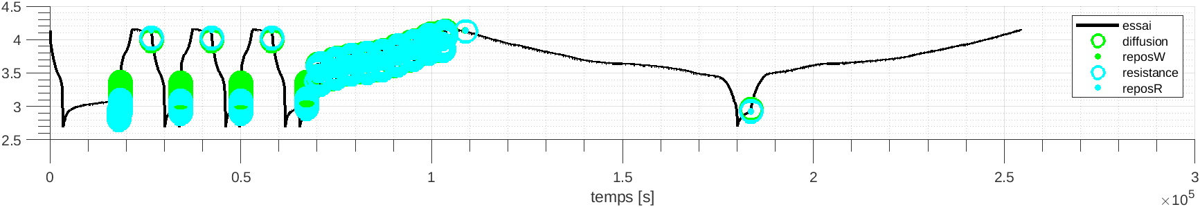
To check if an impedance measurement have been detected by DATTES, the action ‘c’ should be used : [result] = dattes(XMLfile,'cvs');and plotted :[result] = dattes(XMLfile,'Gc');
The impedance measurement detected according to the configuration provided are highlighted as in the following image :
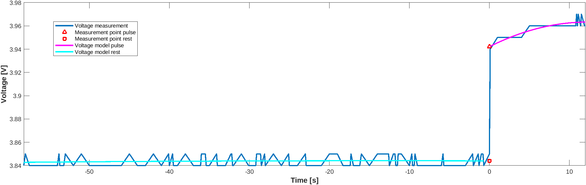
To check if an impedance test have run normally the action ‘gZ’ should be used : [result] = dattes(XMLfile,'gZvs');
Definitions of noisy current and voltage measurements should be adapted to the cycler accuracy. In the following image, a normal impedance measurement for a cycler with a 1 mV accuracy is presented :
Impedance analysis
To analyze the impedance, the action ‘Z’ should be used :
[result] = dattes(XMLfile,'Zvs');
Different parameters will be calculated depending on the handle value chosen for impedance.ident_fcn in the configuration file.
If config.impedance.ident_fcn=@ident_cpe is chosen, the output are :
| Output structure | Field | Array | Unit | Description |
|---|---|---|---|---|
| result | impedance | topology |
Topology of the impedance assembly | |
| result | impedance | Q |
F*s^(alpha-1) | Constant Q |
| result | impedance | alpha |
- | Real number comprised |
| between 0 and 1 | ||||
| result | impedance | R0 |
Ohm | Ohmic resistance |
| result | impedance | time |
s | Time at which impedance is determined |
| result | impedance | dod |
Ah | Depth of discharge at which impedance is determined |
| result | impedance | crate |
- | Current rate at which impedance is determined |
If config.impedance.ident_fcn=@ident_rrc is chosen, the output are :
| Output structure | Field | Array | Unit | Description |
|---|---|---|---|---|
| result | impedance | topology |
Topology of the impedance assembly | |
| result | impedance | r0 |
Ohm | Ohmic resistance |
| result | impedance | r1 |
Ohm | First RC resistance |
| result | impedance | c1 |
F | First RC capacitance |
| result | impedance | r2 |
Ohm | Second RC resistance |
| result | impedance | c2 |
F | Second RC capacitance |
| result | impedance | time |
s | Time at which impedance is determined |
| result | impedance | dod |
Ah | Depth of discharge at which impedance is determined |
| result | impedance | crate |
- | Current rate at which impedance is determined |
Code for visualization
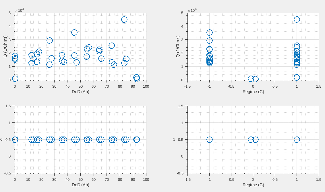
To visualize the impedance, the action ‘GZ’ should be used :
[result] = dattes(XMLfile,'GZ');
The graph should look like
Methodology and Hypothesis
Method
For each pulse considered for impedance calculation, the different arrays are determined respectively in ident_cpe for CPE parameter and ident_rrc for RC parameters.
CPE
Arrays result.impedance.q and result.impedance.alpha are determined in the function calcul_cpe_pulse by defining the Q and alpha value which minimize the error between measurement and model response.
The following code have been adapted from calcul_cpe_pulse to ease readability :
% 1) Q and alpha are determined by minimization of the error between measurement and CPE response

[Q,alpha] = fminsearch(error_cpe_pulse(Q_initial,alpha_initial,I_pulse,t_start_pulse,t_end_pulse,t_measured,U_measured));

% 2)  Error between measurement and CPE response is calculated as the mean value of the quadratic error

function error = error_cpe_pulse(Q_initial,alpha_initial,I_pulse,t_start_pulse,t_end_pulse,t_measured,U_measured)
%error_cpe_pulse model a CPE (Q,alpha) and compare simulation result with measurement
%  Simulation is made in function response_cpe_pulse

U = response_cpe_pulse(Q,alpha,Ip,td,tf,tm);
U = U(:);
Um = Um(:);

error = mean(error_quadratic(Um,U));

end

% 3) CPE response is calculated by the following equations

function U = response_cpe_pulse(Q,alpha,I_pulse,t_start_pulse,t_end_pulse,t_measured)
%response_cpe_pulse simulate CPE response to a constant current.

Utd = echelon(t,td).*(t-td).^alpha/gamma(alpha+1);
Utf = echelon(t,tf).*(t-tf).^alpha/gamma(alpha+1);
U = (Ip/Q)*(Utd-Utf);
end

function x = echelon(t,td)
    x = zeros(size(t));
    x(t>=td)=1;
end
Arrays result.impedance.R0, result.impedance.time, result.impedance.crateand result.impedance.dod are determined as described in the methodology section of resistance analysis tutorial.
RC
Arrays result.impedance.r1, result.impedance.C1, result.impedance.r2 and result.impedance.C2 are determined in the function calcul_rrc by defining the R1, C1, R2 and C2 value which minimize the error between measurement and model response.
The following code have been adapted from calcul_rrc to ease readability :
% 1) Ri and Ci are determined by minimization of the error between measurement and RiCi response

[Ri,Ci] = fminsearch(errorRRC(R0_initial,Ri_initial,Ci_initial,I_measured,t_measured);

% 2)  Error between measurement and RiCi response is calculated as the mean value of the quadratic error

function error = errorRRC(R0_initial,Ri_initial,Ci_initial,I_measured,t_measured)
%errorRRC simulate a RC circuit  and compare the resultat with measurement
%Simulation is made thanks to function reponseRC.


U = rrc_output(tm,Im,Rs,R,C);
U = U(:);
Um = Um(:);

erreur = mean(erreurQuadratique(Um,U))

end

% 3) RRC response is calculated by the following equations

function U = rrc_output(t,I,R0,R,C)
% rrc_output calculate the voltage response of a R0+RC circuit
%
U = I.*R0;
for ind = 1:length(R)
Urc = rc_output(t,I,R(ind),C(ind));
U = U+Urc;
end
end
Arrays result.impedance.R0, result.impedance.time, result.impedance.crateand result.impedance.dod are determined as described in the methodology section of resistance analysis tutorial.
Key parameters for the calculation
The seven key parameters for the calculation of the CPE and RC impedances are :
- config.impedance.pulse_min_duration
- config.impedance.pulse_max_duration
- config.impedance.rest_min_duration
- config.impedance.fixed_params
- config.impedance.initial_params
- config.impedance.pZ
- config.test.capacity
Assumptions and possible simplifications
No major assumptions or simplifications have been made
Contribute to impedance analysis
A list of open issues related to impedance calculation and visualization may be available here.